The subsurface conditions across Dallas can shift dramatically within a few miles. Consider the contrast between the soft alluvial sediments along the Trinity River floodplain near the Design District and the stiff Eagle Ford Shale that caps much of Highland Park. A standard boring log might suggest uniformity, but seismic velocity tells a different story. Seismic tomography bridges that gap, imaging the transition from weathered overburden to competent bedrock with a level of spatial continuity that discrete sampling alone cannot provide. In our experience, combining refraction and reflection data helps resolve ambiguities when the water table is perched within terrace deposits, a scenario common in older neighborhoods like Lakewood. This non-invasive approach complements direct investigation methods such as SPT drilling by extending the stratigraphic interpretation laterally across the entire site footprint.
Seismic velocity models reveal what boreholes miss: the lateral continuity of weathered rock, buried channels, and potential collapse zones across the entire building footprint.
Methodology and scope
Site-specific factors
The most frequent oversight we encounter in Dallas is relying solely on a limited number of boreholes to characterize a site with highly variable rockhead. Contractors sometimes assume the weathered shale profile is uniform across the pad, only to discover during excavation that the rippability changes abruptly — a hard limestone stringer or an unexpected cavity where the Austin Chalk dissolved. Seismic tomography mitigates this risk by mapping the entire volume between control points. Another common mistake is misclassifying the site class for seismic design: a site near Bachman Lake with thick alluvium might shift from Site Class C to D depending on the shear-wave velocity profile of the upper 100 feet. Performing a combined refraction and MASW survey delivers the Vs30 value needed to comply with the IBC and ASCE 7 seismic provisions, while simultaneously providing the P-wave data required for foundation-level rock quality assessment.
Relevant standards
ASTM D5777 – Seismic Refraction Method, ASTM D7128 – Surface Wave (MASW) Method, ASCE 7-22 – Minimum Design Loads (Chapter 20, Site Classification), IBC 2021 – Seismic Site Class Determination, FHWA-NHI-05-037 – Geotechnical Site Characterization (geophysical methods)
Related services
P-Wave Refraction Tomography
Maps the compressional wave velocity structure for rockhead profiling, rippability assessment, and cavity detection within the upper 30 to 80 feet. Typical source-to-receiver offsets up to 230 feet.
S-Wave Refraction and MASW
Generates shear-wave velocity profiles for Vs30 computation and site class determination per ASCE 7. Horizontal geophones and a cross-line source generate clear S-wave arrivals even in noisy urban settings.
High-Resolution Seismic Reflection
Targets deeper stratigraphy — 100 to 500 feet — to identify faults within the Woodbine and Eagle Ford formations. Uses a small explosive or accelerated weight-drop source with a dense geophone array.
Integrated Geophysical Interpretation
Combines refraction, reflection, and borehole data into a unified geotechnical model. Velocity cross-sections are calibrated against SPT N-values and lab test results for direct use in foundation design.
Typical parameters
Quick answers
How much does a seismic refraction survey cost for a typical Dallas building site?
For a standard commercial lot in the Dallas-Fort Worth area, a P-wave refraction survey with 24 to 48 channels typically ranges from US$2,820 to US$5,940, depending on the spread length, number of shots, and site access conditions. Sites requiring both refraction and MASW for Vs30 determination fall in the upper portion of that range.
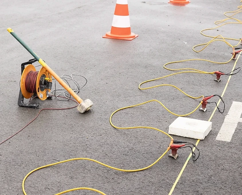
Can seismic refraction work on paved surfaces like a parking lot?
Yes, with some limitations. Geophones can be planted in soil adjacent to the pavement or coupled to asphalt using base plates and wax, though the signal quality depends on the thickness and condition of the asphalt. In urban Dallas settings, we often use a weight-drop source on pavement to reduce surface-wave noise, or deploy the line along a landscaped perimeter where soil coupling is better.
What depth can seismic refraction reach in the Eagle Ford Shale?
The investigation depth depends on the geophone spread length — typically 20 to 30 percent of the total array length. For a 230-foot spread, we can reliably image to approximately 60 to 70 feet in weathered Eagle Ford Shale. Where bedrock is shallower and velocities exceed 8,000 ft/s, the energy refracts at a high angle and the method still resolves the top-of-rock interface accurately.
How do you determine the site class for IBC seismic design using geophysics?
We compute the average shear-wave velocity of the upper 100 feet (Vs30) using either a combined MASW and refraction survey or a downhole seismic test. The Vs30 value maps directly to the ASCE 7 site classes: values between 600 and 1,200 ft/s correspond to Site Class C, while 300 to 600 ft/s indicate Site Class D, which is common in Trinity River alluvium. The result feeds directly into the structural engineer's seismic base shear calculation.